Controlling traffic flows is one of the benefits you get when using RSVP to signal LSPs. Using Junos OS, you are able to do this in quite a number of ways. This article aims to explain some of these options. After a brief CSPF recap, we’ll have a look at how we can exercise control over the path an LSP takes.
When an RSVP signaled LSP needs to be set up, the ingress LSR computes the path the LSP should take. This path is computed using information that is stored inside the Traffic Engineering Database, or TED. Information inside the TED is provided by an IGPs traffic engineering extensions. These traffic engineering extensions can be provided by OSPF or IS-IS.
The computation of the LSPs is done using the Constrained Shortest Path First algorithm, or CSPF. When an LSR computes an LSP using this CSPF, it takes into account what the constraints of an LSP are. The LSR first prunes the links that do not meet these constraints from the TED. After all relevant links are pruned, the shortest path is computed based on the remaining links still present in the TED.
An LSR will compute LSPs one at a time, starting with the highest priority LSP (equal priority LSPs are computed in alphabetical order). For every LSP, CSPF will follow these steps:
- Prune the TED of links that do not have enough bandwidth available
- Prune the TED of links that lack the necessary colors
- Prune the TED of links that contain a color that should be excluded
- If the remaining paths are equal cost paths, choose the one whose last-hop address is the same as the LSPs destination
- If several paths remain, select the path with the fewest hops
- If multiple equal-cost paths remain, apply the CSPF load-balancing rule to the LSPs
As soon as the computations for an individual LSP are completed, the calculated path is written down in a list called ‘ERO’ (Explicit Route Object). The ERO is a list of all the links that the LSP should traverse. This list is then put into an RSVP path message and this RSVP path message is used to signal the LSP.
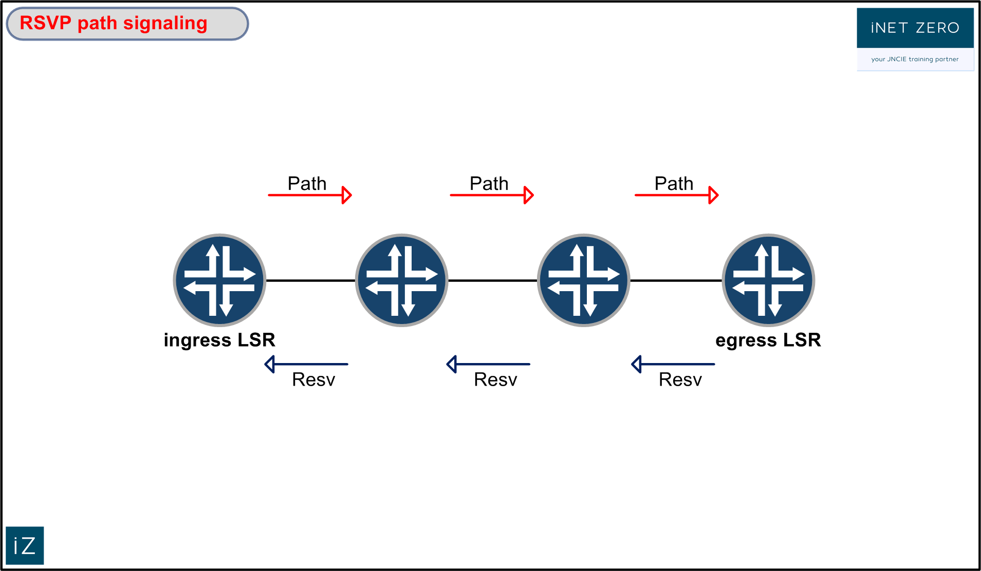
The RSVP path message travels from the ingress LSR downstream to the egress LSR. Every router along the way inspects the ERO inside path message and removes its own IP address from that list. After this, the message is send further downstream to the router that is next on this list.
For an RSVP path message, the egress LSR is the last stop. The egress router will send an RSVP Resv message in return to the Path message. The path that the Resv message takes is the same as the Path message, only in reverse. The Resv message is used to reserve the resources for the LSP. Every router will use the Resv message to tell the upstream router what label to install into their LIB.
After an LSP is signaled, there are two easy ways to find out what the content of the ERO is. You can issue a ‘show mpls lsp name xx extensive’ and look for the ‘Computed ERO’. Additionally, you can issue a ‘show rsvp session name xx extensive’ and look for the ‘Explct route’ information.
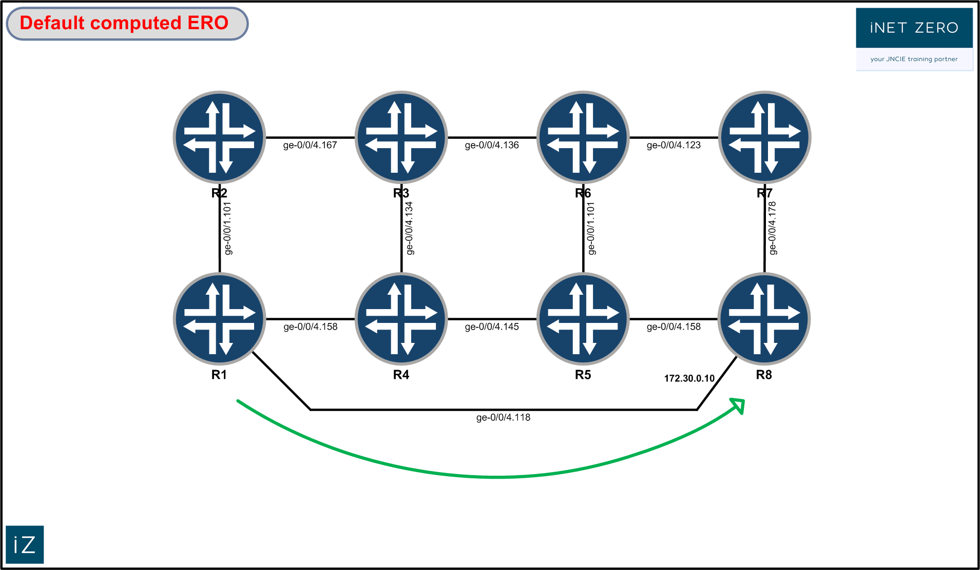
Default computed ERO behavior:
Let’s look at the default behavior of the most basic RSVP signaled LSP first. The most basic configuration for an LSP from R1 towards R8 could be the following:
set protocols mpls label-switched-path to-r8-default to 172.30.5.8
This LSP will follow the lowest IGP cost to the destination. In our scenario, there is a link directly connecting R1 to R8. Since all links in our scenario have the same metric (10), this will be the shortest path.
To verify how the LSP was set up, we issue the following command:
lab@vmx1-sun# show mpls lsp ingress name to-r8-default detail
Ingress LSP: 4 sessions

172.30.5.8
  From: 172.30.5.1, State: Up, ActiveRoute: 0, LSPname: to-r8-default
  ActivePath:  (primary)
  LSPtype: Static Configured, Penultimate hop popping
  LoadBalance: Random
  Encoding type: Packet, Switching type: Packet, GPID: IPv4
 *Primary                    State: Up
    Priorities: 7 0
    SmartOptimizeTimer: 180
    Computed ERO (S [L] denotes strict [loose] hops): (CSPF metric: 10)
 172.30.0.10 S
    Received RRO (ProtectionFlag 1=Available 2=InUse 4=B/W 8=Node 10=SoftPreempt 20=Node-ID):
          172.30.0.10
Total 1 displayed, Up 1, Down 0
The LSP was signaled across the path that had the lowest cumulative cost according to our IGP.
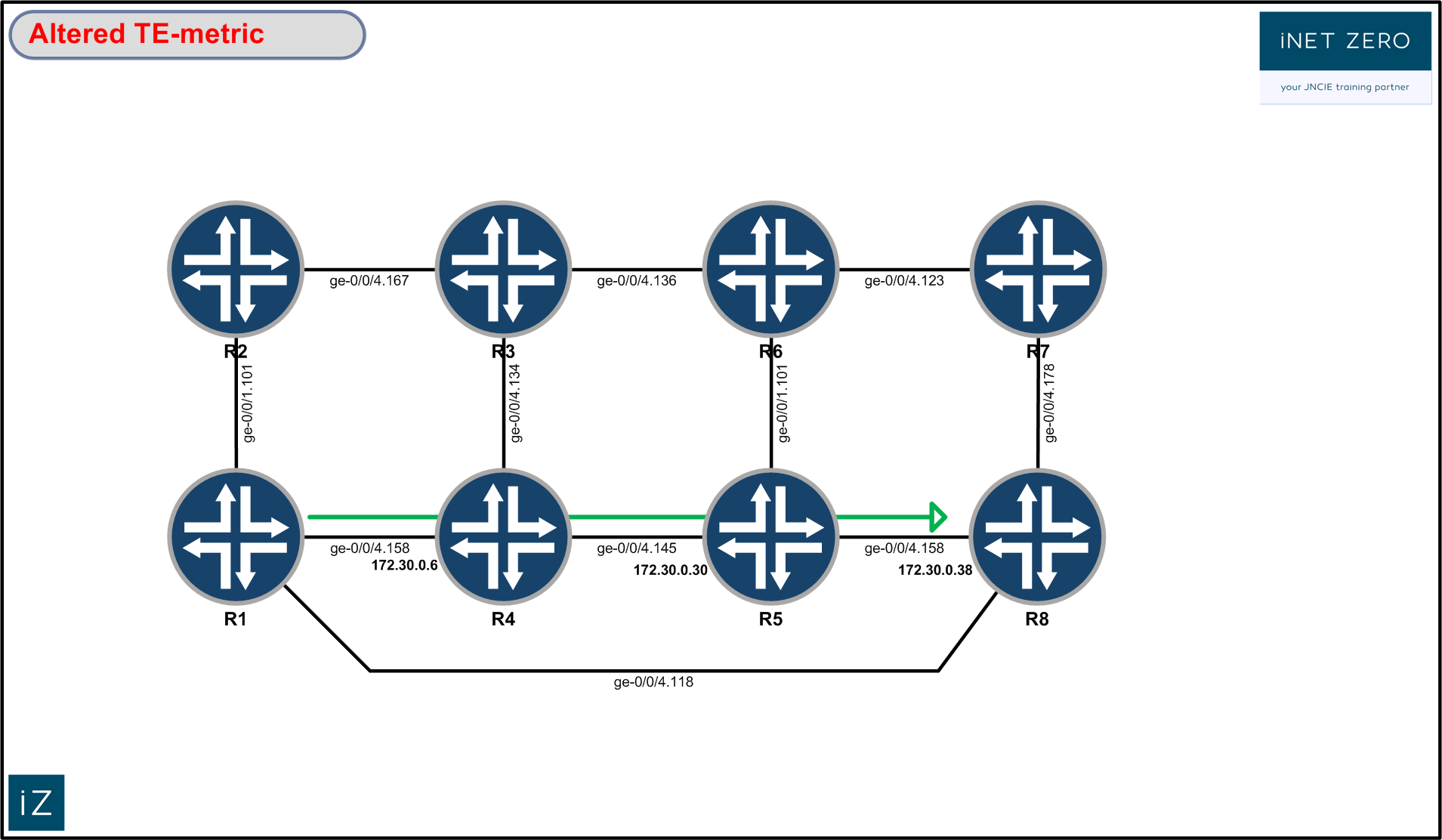
Changing the ERO by changing the metric:
A quick and easy way to force the LSP to take another route would be by changing the metric of this link. When we choose to do so, we can alter the cost for the link in all IGP related calculations or we can change the cost of this link for RSVP-TE purposes only. Let’s change the link cost in ISIS for RSVP-TE purposes only like this:
set protocols isis interface ge-0/0/4.118 level 1 te-metric 100
After committing this change, we force the router to signal the LSP again. We do this by clearing the LSP. After the LSP is cleared using the ‘clear mpls lsp’ command, it is automatically set up again using the new metrics:
To verify that the computed ERO now differs from our previous output, we issue the same show command again:
lab@vmx1-sun# show mpls lsp ingress name to-r8-default detail
Ingress LSP: 4 sessions

172.30.5.8
  From: 172.30.5.1, State: Up, ActiveRoute: 0, LSPname: to-r8-default
  ActivePath:  (primary)
  LSPtype: Static Configured, Penultimate hop popping
  LoadBalance: Random
  Encoding type: Packet, Switching type: Packet, GPID: IPv4
 *Primary                    State: Up
    Priorities: 7 0
    SmartOptimizeTimer: 180
    Computed ERO (S [L] denotes strict [loose] hops): (CSPF metric: 30)
 172.30.0.6 S 172.30.0.30 S 172.30.0.38 S
    Received RRO (ProtectionFlag 1=Available 2=InUse 4=B/W 8=Node 10=SoftPreempt 20=Node-ID):
          172.30.0.6 172.30.0.30 172.30.0.38
Total 1 displayed, Up 1, Down 0
By altering the te-metric, we only alter the cost of the link for calculations done by the CSPF algorithm. We can verify this by looking at the information in the TED. We can look at the information stored in the TED by issuing the following command (the IP address is the router-id of the ingress LSR):
lab@vmx8-procyon# show ted database extensive 172.30.5.1
TED database: 9 ISIS nodes 9 INET nodes
NodeID: vmx1-sun.00(172.30.5.1)
  Type: Rtr, Age: 1 secs, LinkIn: 3, LinkOut: 3
  Protocol: IS-IS(1)
   172.30.5.1
    To: vmx8-procyon.00(172.30.5.8), Local: 172.30.0.9, Remote: 172.30.0.10
      Local interface index: 332, Remote interface index: 325
      Color: 0
      Metric: 100
      IGP metric: 10
      Static BW: 1000Mbps
      Reservable BW: 1000Mbps
      Available BW [priority] bps:
          [0] 1000Mbps     [1] 1000Mbps    [2] 1000Mbps    [3] 1000Mbps
          [4] 1000Mbps     [5] 1000Mbps    [6] 1000Mbps    [7] 1000Mbps
      Interface Switching Capability Descriptor(1):
        Switching type: Packet
        Encoding type: Packet
        Maximum LSP BW [priority] bps:
          [0] 1000Mbps     [1] 1000Mbps    [2] 1000Mbps    [3] 1000Mbps
          [4] 1000Mbps     [5] 1000Mbps    [6] 1000Mbps    [7] 1000Mbps
The metric that is listed first is the TE-metric. This metric was used for the CSPF calculations. The IGP metric, used to calculate the routes in the inet.0 table, remains unaltered. Both OSPF and IS-IS allow us to do this.
As an alternative to the ‘show ted database extensive’ command, we could have also used the ‘show isis database’ with the extensive option to verify the same thing (‘show ospf database opaque-area extensive’ when running OSPF).
Imposing bandwidth constraints:
The previously configured te-metric has been removed from the configuration. We now want to signal an RSVP LSP and influence the path by manipulating the available bandwidth.
By default, a Juniper router allows you to use 100% of the bandwidth of an RSVP enabled link. In our scenario, all of the links are 1Gbit:
lab@vmx1-sun# show rsvp interface
RSVP interface: 4 active
                  Active Subscr- Static      Available   Reserved    Highwater
Interface   State resv   iption  BW          BW          BW          mark
ge-0/0/1.101Up         4   100%  1000Mbps    1000Mbps    0bps        900Mbps
ge-0/0/4.114Up         2   100%  1000Mbps    1000Mbps    0bps        900Mbps
ge-0/0/4.118Up         1   100%  1000Mbps    1000Mbps    0bps        900Mbps
Before imposing a bandwidth constraint on the LSP, we first reduce the available bandwidth on the link between R1 and R8:
set protocols rsvp interface ge-0/0/4.118 subscription 89
The subscription configuration command reduces the available bandwidth from 1Gbit to 890Mbps.
lab@vmx1-sun# show rsvp interface ge-0/0/4.118
                  Active Subscr- Static      Available   Reserved    Highwater
Interface   State resv   iption  BW          BW          BW          mark
ge-0/0/4.118Up         0    89%  1000Mbps    890Mbps     0bps        900Mbps
To demonstrate that we can use the bandwidth to control the path the LSP will follow, let’s configure an LSP like this:
set protocols mpls label-switched-path to-r8-bandwidth to 172.30.5.8
set protocols mpls label-switched-path to-r8-bandwidth bandwidth 900m
The LSP was configured to reserve 900m on every link ( an LSP does not require any bandwidth by default) . Because of the previous configuration, CSPF will only consider links that have 900m or more bandwidth available. As a result of this configuration, the LSP will not be able to traverse the direct link towards R8. After the LSP is set up, we can observe the following:
lab@vmx1-sun# show mpls lsp name to-r8-bandwidth detail
Ingress LSP: 4 sessions

172.30.5.8
  From: 172.30.5.1, State: Up, ActiveRoute: 0, LSPname: to-r8-bandwidth
  ActivePath:  (primary)
  LSPtype: Static Configured, Penultimate hop popping
  LoadBalance: Random
  Encoding type: Packet, Switching type: Packet, GPID: IPv4
 *Primary                    State: Up
    Priorities: 7 0
    Bandwidth: 900Mbps
    SmartOptimizeTimer: 180
    Computed ERO (S [L] denotes strict [loose] hops): (CSPF metric: 30)
 172.30.0.6 S 172.30.0.30 S 172.30.0.38 S
    Received RRO (ProtectionFlag 1=Available 2=InUse 4=B/W 8=Node 10=SoftPreempt 20=Node-ID):
          172.30.0.6 172.30.0.30 172.30.0.38
Total 1 displayed, Up 1, Down 0
Because of the imposed bandwidth constraint, the LSP was not signaled across the direct link. It took the following path instead:

Using link colors.
Before we can manipulate the path of an LSP using link colors, we need to configure the colors (a.k.a. administrative groups) on every router:
set protocols mpls admin-groups red 0
set protocols mpls admin-groups blue 2
After this, we can start assigning colors to the interfaces. We assign the following colors to the links in our topology (no admin-groups are assigned to the black links):
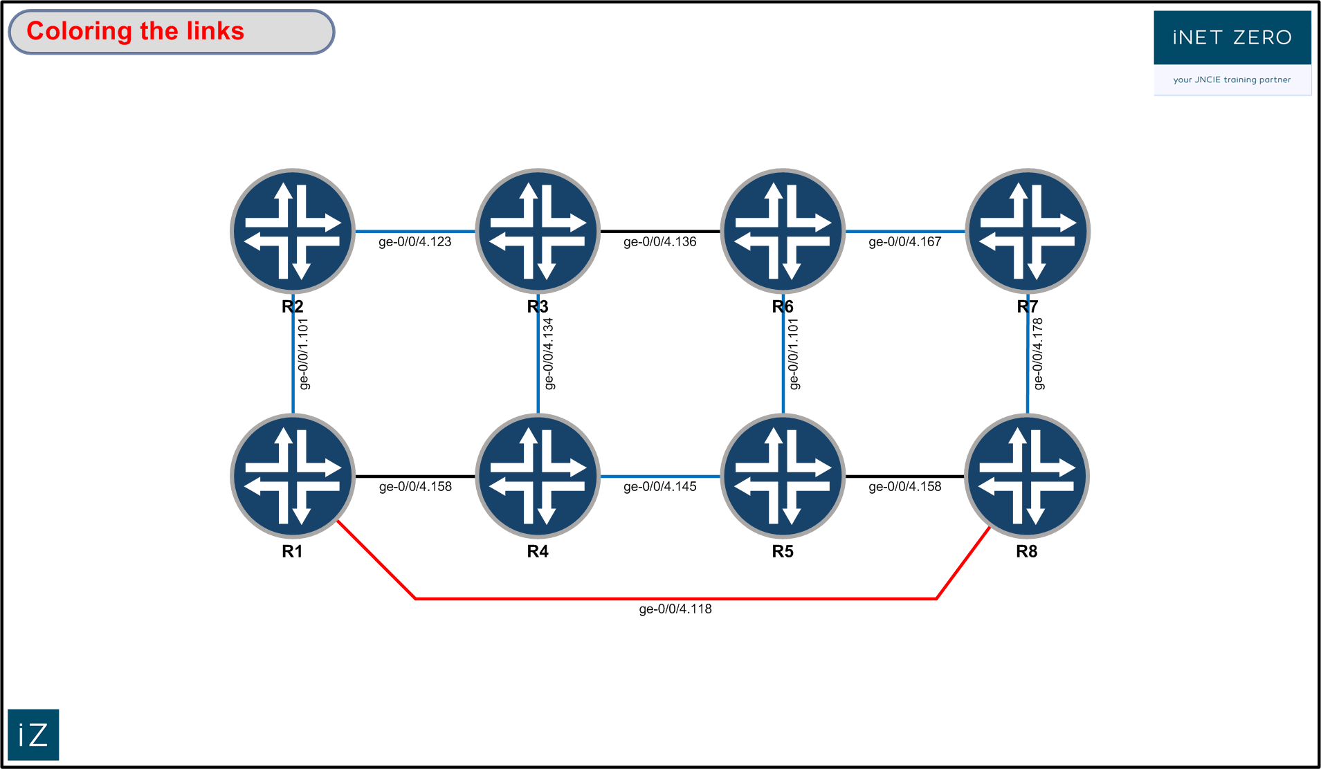
As an example, we’ll look at the configuration that is applied to R8, where we leave the ge-0/0/4.158 interface colorless:
set protocols mpls interface ge-0/0/4.118 admin-group red
set protocols mpls interface ge-0/0/4.178 admin-group blue
set protocols mpls interface ge-0/0/4.158
To verify the result of this configuration, we can issue the following command:
lab@vmx8-procyon# show mpls interface
Interface        State       Administrative groups (x: extended)
ge-0/0/4.118     Up          red
ge-0/0/4.158     Up
ge-0/0/4.178     Up          blue
Let’s create an LSP from R1 to R8 and use colors to influence the paths of that LSP. What we want is to end up with a path that crosses only blue links, and a second path that excludes all red links:
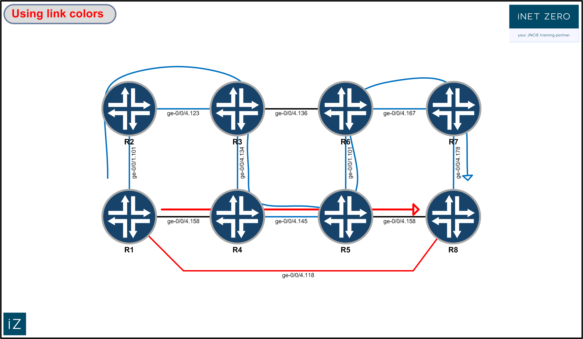
set protocols mpls label-switched-path to-r8-color to 172.30.5.8
set protocols mpls label-switched-path to-r8-color primary no-red admin-group exclude red
set protocols mpls label-switched-path to-r8-color secondary blue standby
set protocols mpls label-switched-path to-r8-color secondary blue admin-group include-all blue

set protocols mpls path no-red
set protocols mpls path blue
This configuration will make R1 signal an LSP with two paths. For the primary path, the constraint is that no red links can be used. After pruning all red links in the network, this path will be computed based on the lowest IGP cost. Note that the path will only exclude red links. CSPF will not prune the blue links or the links without any color.
The secondary path, which will be signaled due to the standby keyword, will only consider blue links.
The configuration of the named paths, under the [ protocols mpls path], serves no real purpose in this example. I just wanted a path name that corresponds to the link color referenced in the LSP configuration. The paths could have been configured with any other name.
Let’s have a look at the result of our configuration:
lab@vmx1-sun# show mpls lsp ingress name to-r8-color detail
Ingress LSP: 4 sessions

172.30.5.8
  From: 172.30.5.1, State: Up, ActiveRoute: 0, LSPname: to-r8-color
  ActivePath: no-red (primary)
  LSPtype: Static Configured, Penultimate hop popping
  LoadBalance: Random
  Encoding type: Packet, Switching type: Packet, GPID: IPv4
 *Primary   no-red           State: Up
    Priorities: 7 0
    SmartOptimizeTimer: 180
          Exclude: red
    Computed ERO (S [L] denotes strict [loose] hops): (CSPF metric: 30)
 172.30.0.2 S 172.30.0.18 S 172.30.0.46 S
    Received RRO (ProtectionFlag 1=Available 2=InUse 4=B/W 8=Node 10=SoftPreempt 20=Node-ID):
          172.30.0.2 172.30.0.18 172.30.0.46
  Standby   blue             State: Up
    Priorities: 7 0
    SmartOptimizeTimer: 180
          Include All: blue
    Computed ERO (S [L] denotes strict [loose] hops): (CSPF metric: 70)
 172.30.0.2 S 172.30.0.14 S 172.30.0.22 S 172.30.0.30 S 172.30.0.34 S 172.30.0.42 S 172.30.0.46 S
    Received RRO (ProtectionFlag 1=Available 2=InUse 4=B/W 8=Node 10=SoftPreempt 20=Node-ID):
          172.30.0.2 172.30.0.14 172.30.0.22 172.30.0.30 172.30.0.34 172.30.0.42 172.30.0.46
Total 1 displayed, Up 1, Down 0
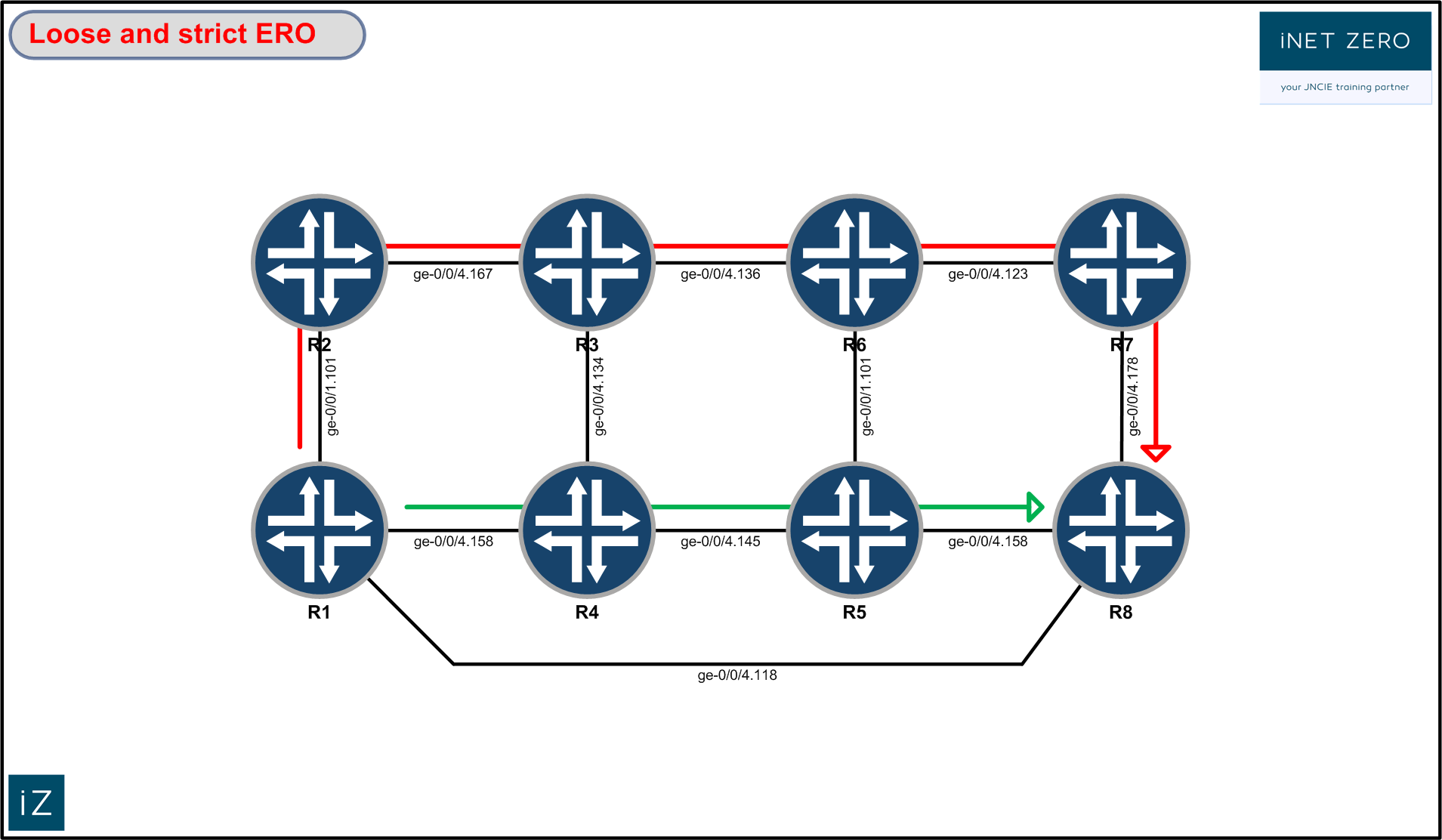
Configuring the ERO.
Another way to manipulate the path of an RSVP-signaled LSP is through the manual configuration of the ERO. This is a very straightforward and deterministic way to configure an LSP. Let’s configure an LSP with a ‘strict’ primary path and a ‘loose’ secondary path.
A manually configured strict path is a list of IP addresses that specify the path on a hop-by-hop basis. Every hop must be connected to the previous hop.
A loose path is a list of IP addresses that the LSP needs to visit somewhere along the way. The routing-table is used to determine the path towards a loose hop.
In the following example, we configure the primary path go through the routers ‘r2-r3-r6-r7-r8’ in this exact order. The secondary path is configured with a loose path that MUST visit R5 somewhere. For this path, the router will first calculate the lowest cost path to R5. After that, it will calculate the lowest cost path towards the egress LSP.
These requirements can be achieved by applying the following configuration:
set protocols mpls label-switched-path to-r8-ero to 172.30.5.8
set protocols mpls label-switched-path to-r8-ero primary r2-r3-r6-r7-r8
set protocols mpls label-switched-path to-r8-ero secondary via-r5 standby

set protocols mpls path r2-r3-r6-r7-r8 172.30.5.2 strict
set protocols mpls path r2-r3-r6-r7-r8 172.30.5.3 strict
set protocols mpls path r2-r3-r6-r7-r8 172.30.5.6 strict
set protocols mpls path r2-r3-r6-r7-r8 172.30.5.7 strict

set protocols mpls path via-r5 172.30.5.5 loose
The manual configuration of the ERO takes place in the path stanza. A tip to make things easier is to use the loopback IP addresses of the routers when configuring the path. This is what was done here as well. Keep in mind that even though the loopback IP addresses were configured, the IP addresses you’ll see listed in the ERO will correspond to the IP addresses that are encountered on the links in the network.
The LSPs that are signaled as a result of this configuration should be the following:
To verify this, we issue the following command:
lab@vmx1-sun# show mpls lsp name to-r8-ero detail
Ingress LSP: 4 sessions

172.30.5.8
  From: 172.30.5.1, State: Up, ActiveRoute: 0, LSPname: to-r8-ero
  ActivePath: r2-r3-r6-r7-r8 (primary)
  LSPtype: Static Configured, Penultimate hop popping
  LoadBalance: Random
  Encoding type: Packet, Switching type: Packet, GPID: IPv4
 *Primary   r2-r3-r6-r7-r8   State: Up
    Priorities: 7 0
    SmartOptimizeTimer: 180
    Computed ERO (S [L] denotes strict [loose] hops): (CSPF metric: 50)
 172.30.0.2 S 172.30.0.14 S 172.30.0.26 S 172.30.0.42 S 172.30.0.46 S
    Received RRO (ProtectionFlag 1=Available 2=InUse 4=B/W 8=Node 10=SoftPreempt 20=Node-ID):
          172.30.0.2 172.30.0.14 172.30.0.26 172.30.0.42 172.30.0.46
  Standby   via-r5           State: Up
    Priorities: 7 0
    SmartOptimizeTimer: 180
    Computed ERO (S [L] denotes strict [loose] hops): (CSPF metric: 30)
 172.30.0.6 S 172.30.0.30 S 172.30.0.38 S
    Received RRO (ProtectionFlag 1=Available 2=InUse 4=B/W 8=Node 10=SoftPreempt 20=Node-ID):
          172.30.0.6 172.30.0.30 172.30.0.38
Total 1 displayed, Up 1, Down 0
In this example, we configured a strict and a loose path. Note that it is possible to mix strict and loose in the same path.
RSVP puts you in control and lets you determine how traffic should flow across your MPLS network. In this post, we covered some of the basic ways in which we can exercise control over RSVP signaled paths. We changed the link metric, configured a bandwidth constraint, colored links and manually configured the ERO.
Note that in addition to imposing constraints on an LSP, Junos OS has many additional options available to achieve an even higher degree of control. Junos OS allows you to map traffic onto specific RSVP signaled LSPs based on numerous characteristics. and there are lots of additional options that can be activated on a per-LSP basis. Link-protection, policing, altering the setup and hold-priority just to name a few.
RSVP puts you in control of the network. To test yourself and to see how well-versed you are configuring and troubleshooting RSVP signaled LSPs, consider using the iNET ZERO JNCIE-SP books and labs.
