The QFX is a very versatile switch with a lot of deployment options. In this article, I want to go over a scenario in which 4 QFX switches are deployed to form a controllerless-overlay:
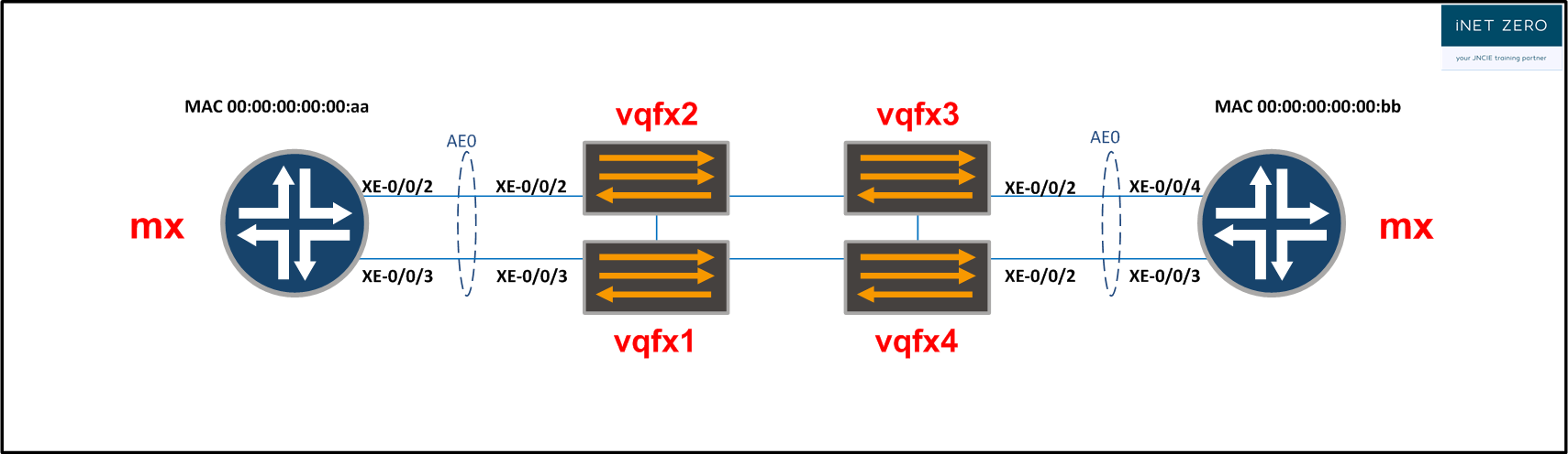
The main characters here are the QFX switches. As an overlay, they will offer an all-active layer 2 connection to both MX routers.
In this walkthrough, I will cover the following configuration steps:
- Underlay.
- Signaling for the overlay.
- QFX-switch level EVPN.
- Multihoming and the addition of a VXLAN segment.
- Adding an additional VXLAN segment.
Configuring the underlay.
The underlay network has one main function: providing IP connectivity between the loopback IP addresses of the switches. To achieve our goal, really any protocol would work. We can use BGP, IS-IS, OSPF or something else. For this example, I chose to use OSPF:
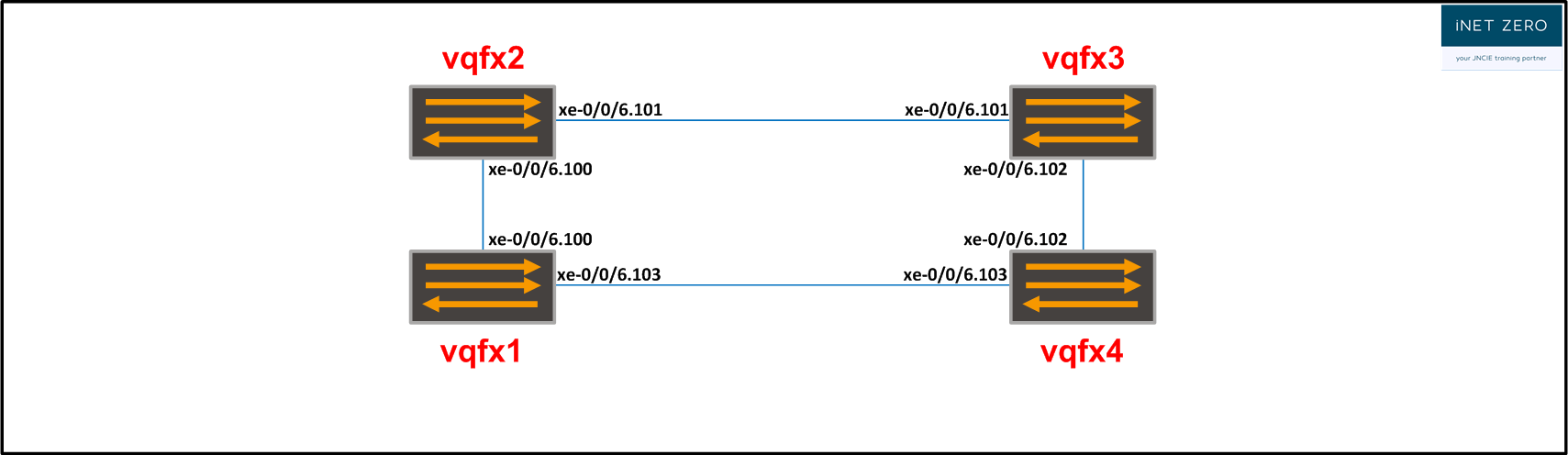
vQFX1:

set protocols ospf area 0.0.0.0 interface xe-0/0/6.100
set protocols ospf area 0.0.0.0 interface xe-0/0/6.103
set protocols ospf area 0.0.0.0 interface lo0.0 passive


vQFX2:

set protocols ospf area 0.0.0.0 interface xe-0/0/6.100
set protocols ospf area 0.0.0.0 interface xe-0/0/6.101
set protocols ospf area 0.0.0.0 interface lo0.0 passive


vQFX3:

set protocols ospf area 0.0.0.0 interface xe-0/0/6.101
set protocols ospf area 0.0.0.0 interface xe-0/0/6.102
set protocols ospf area 0.0.0.0 interface lo0.0 passive


vQFX4:

set protocols ospf area 0.0.0.0 interface xe-0/0/6.102
set protocols ospf area 0.0.0.0 interface xe-0/0/6.103
set protocols ospf area 0.0.0.0 interface lo0.0 passive
Configuring signaling for the overlay.
When Juniper QFX switches are used to build a controllerless overlay, control plane signaling is taken care of by BGP. The overlay is not very big, so instead of turning to any of the BGP scaling mechanisms, we simply configure a full-mesh. Every BGP session needs to support the EVPN address family. For the sake of stability, we source the BGP sessions from the loopback interface on every QFX:
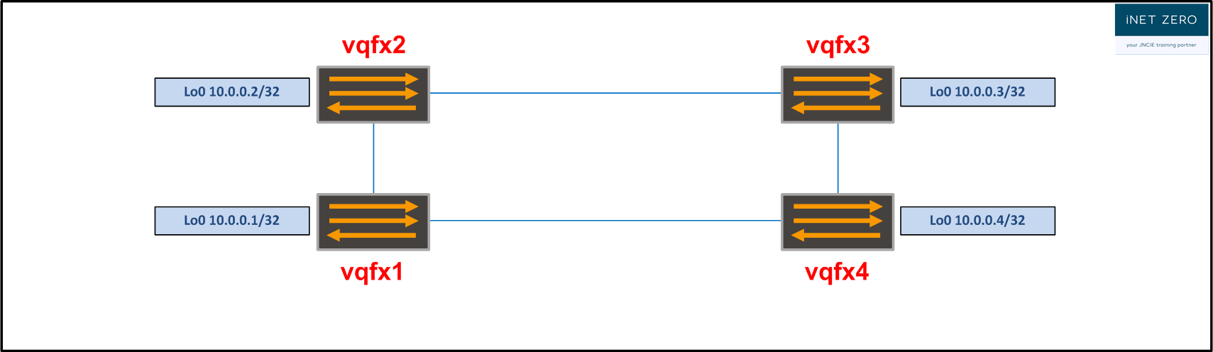
vQFX1:

set routing-options autonomous-system 65400

set protocols bgp group overlay type internal
set protocols bgp group overlay local-address 10.0.0.1
set protocols bgp group overlay family evpn signaling
set protocols bgp group overlay neighbor 10.0.0.2
set protocols bgp group overlay neighbor 10.0.0.3
set protocols bgp group overlay neighbor 10.0.0.4


vQFX2:

set routing-options autonomous-system 65400

set protocols bgp group overlay type internal
set protocols bgp group overlay local-address 10.0.0.2
set protocols bgp group overlay family evpn signaling
set protocols bgp group overlay neighbor 10.0.0.1
set protocols bgp group overlay neighbor 10.0.0.3
set protocols bgp group overlay neighbor 10.0.0.4


vQFX3:

set routing-options autonomous-system 65400

set protocols bgp group overlay type internal
set protocols bgp group overlay local-address 10.0.0.3
set protocols bgp group overlay family evpn signaling
set protocols bgp group overlay neighbor 10.0.0.1
set protocols bgp group overlay neighbor 10.0.0.2
set protocols bgp group overlay neighbor 10.0.0.4


vQFX4:

set routing-options autonomous-system 65400

set protocols bgp group overlay type internal
set protocols bgp group overlay local-address 10.0.0.4
set protocols bgp group overlay family evpn signaling
set protocols bgp group overlay neighbor 10.0.0.1
set protocols bgp group overlay neighbor 10.0.0.2
set protocols bgp group overlay neighbor 10.0.0.3
Configure QFX-switch level EVPN
To enable a single QFX to be part of a controllerless overlay, we need to define several switch-level parameters. For this scenario, we want to build a controllerless overlay that uses VXLAN encapsulation and ingress replication. We also want to allow the switch to import any signaled VXLAN segments we configure later on with minimal configuration overhead. To this end, we configure the following parameters under the [ protocols evpn ] stanza:
vQFX1:

set protocols evpn encapsulation vxlan
set protocols evpn extended-vni-list all
set protocols evpn multicast-mode ingress-replication
Next up is the configuration of the switch-options. Here we configure the vtep-source-interface, the route-distinguisher and the route-target:
vQFX1:

set switch-options vtep-source-interface lo0.0
set switch-options route-distinguisher 10.0.0.1:65400
set switch-options vrf-target target:100:100
set switch-options vrf-target auto
We have configured two vrf-target values. The first value, vrf-target:100:100 will be attached to type 1 routes. The auto statement will ensure that for every VXLAN segment, a route-target is generated automatically. Both vrf-target statements will cause for the QFX to create and apply ‘hidden’ policies. These policies take care of the route-target import and export.
Last step here is to configure a router-ID. In order to have the QFX commit, the router-id has to match the lo0 address:
vQFX1:

set routing-options router-id 10.0.0.1
The QFX-switch level configuration shown here is for vQFX1. The other vQFX switches can be configured with a similar configuration. Only two things differ, the route-distinguisher value and the router-id. On the other switches, instead of using 10.0.0.1, the IP address configured as the loopback is used.
Configure Multihoming and a VXLAN segment.
Even though we have prepared every QFX for switch-level EVPN, nothing is happing yet. There is no signaling going on in our overlay and forwarding across VXLAN tunnels is not possible. Let’s change that by adding the multihomed connections the MX routers as well as adding a VXLAN segment.
During this part of the configuration, we need to:
- enable each QFX for LAGs
- assign interfaces to the LAGs
- configure the LAGs as multihomed Ethernet Segments
- create the VXLAN segment and add that to the LAG interfaces
As far as the LAG is concerned, we have a few things to bear in mind. First of all, the MX routers need to think that they are communicating with a single device. To this end, we configure the same lacp system-id on the QFX pairs. Another thing is the esi configuration. We will configure the Ethernet segment to be all-active and we need to specify a unique ESI on each QFX pair. The ESI identifier needs to be unique on a network-wide basis.
After taking into account those specificities, the rest of the LAG configuration is exactly like a standard trunk interface. On each QFX, we conclude the configuration with the creation of a VXLAN segment. In this case, this is really nothing more than the configuration of a VLAN with a VNI value.
vQFX1:

set chassis aggregated-devices ethernet device-count 1

set interfaces xe-0/0/3 ether-options 802.3ad ae0

set interfaces ae0 esi 00:12:12:12:12:12:12:12:12:12
set interfaces ae0 esi all-active
set interfaces ae0 aggregated-ether-options lacp active
set interfaces ae0 aggregated-ether-options lacp system-id 12:12:12:12:12:12
set interfaces ae0 unit 0 family ethernet-switching interface-mode trunk
set interfaces ae0 unit 0 family ethernet-switching vlan members 100

set vlans vlan-100 vlan-id 100 vxlan vni 100


vQFX2:

set chassis aggregated-devices ethernet device-count 1

set interfaces xe-0/0/2 ether-options 802.3ad ae0

set interfaces ae0 esi 00:12:12:12:12:12:12:12:12:12
set interfaces ae0 esi all-active
set interfaces ae0 aggregated-ether-options lacp active
set interfaces ae0 aggregated-ether-options lacp system-id 12:12:12:12:12:12
set interfaces ae0 unit 0 family ethernet-switching interface-mode trunk
set interfaces ae0 unit 0 family ethernet-switching vlan members 100

set vlans vlan-100 vlan-id 100 vxlan vni 100


vQFX3:

set chassis aggregated-devices ethernet device-count 1

set interfaces xe-0/0/2 ether-options 802.3ad ae0

set interfaces ae0 esi 00:34:34:34:34:34:34:34:34:34
set interfaces ae0 esi all-active
set interfaces ae0 aggregated-ether-options lacp active
set interfaces ae0 aggregated-ether-options lacp system-id 34:34:34:34:34:34
set interfaces ae0 unit 0 family ethernet-switching interface-mode trunk
set interfaces ae0 unit 0 family ethernet-switching vlan members 100

set vlans vlan-100 vlan-id 100 vxlan vni 100


vQFX4:

set chassis aggregated-devices ethernet device-count 1

set interfaces xe-0/0/2 ether-options 802.3ad ae0

set interfaces ae0 esi 00:34:34:34:34:34:34:34:34:34
set interfaces ae0 esi all-active
set interfaces ae0 aggregated-ether-options lacp active
set interfaces ae0 aggregated-ether-options lacp system-id 34:34:34:34:34:34
set interfaces ae0 unit 0 family ethernet-switching interface-mode trunk
set interfaces ae0 unit 0 family ethernet-switching vlan members 100

set vlans vlan-100 vlan-id 100 vxlan vni 100
Adding an additional VXLAN segment.
Now that we have completed our controllerless overlay, let’s have a look at the configuration overhead for adding additional VXLAN segments.
To add a VXLAN segment for VLAN 101 on every multihomed interface, we need to configure the following on every QFX device:
set interfaces ae0 unit 0 family ethernet-switching vlan members 101
set vlans vlan-101 vlan-id 101 vxlan vni 101
Verification:
Let’s start out verifying what we can from the MX point of view. We can see that the LAG between MX1 and the QFX switches is operational:
jncie@vMX1> show lacp interfaces extensive
Aggregated interface: ae0
    LACP state:       Role   Exp   Def  Dist  Col  Syn  Aggr  Timeout  Activity
      xe-0/0/2       Actor    No    No   Yes  Yes  Yes   Yes     Fast    Active
      xe-0/0/2     Partner    No    No   Yes  Yes  Yes   Yes     Fast    Active
      xe-0/0/3       Actor    No    No   Yes  Yes  Yes   Yes     Fast    Active
      xe-0/0/3     Partner    No    No   Yes  Yes  Yes   Yes     Fast    Active
    LACP protocol:        Receive State  Transmit State          Mux State
      xe-0/0/2                  Current   Fast periodic Collecting distributing
      xe-0/0/3                  Current   Fast periodic Collecting distributing
    LACP info:        Role     System             System       Port     Port    Port
                             priority         identifier   priority   number     key
      xe-0/0/2       Actor        127  00:05:86:72:fb:c0        127        3       1
      xe-0/0/2     Partner        127  12:12:12:12:12:12        127        1       1
      xe-0/0/3       Actor        127  00:05:86:72:fb:c0        127        4       1
      xe-0/0/3     Partner        127  12:12:12:12:12:12        127        1       1
Sending traffic across both VXLAN segments:
jncie@vMX1> ping 192.168.1.2 rapid
PING 192.168.1.2 (192.168.1.2): 56 data bytes
!!!!!
--- 192.168.1.2 ping statistics ---
5 packets transmitted, 5 packets received, 0% packet loss
round-trip min/avg/max/stddev = 52.196/65.551/73.717/7.806 ms


jncie@vMX1> ping 192.168.2.2 rapid
PING 192.168.2.2 (192.168.2.2): 56 data bytes
!!!!!
--- 192.168.2.2 ping statistics ---
5 packets transmitted, 5 packets received, 0% packet loss
round-trip min/avg/max/stddev = 54.500/135.347/285.082/90.370 ms
Now on to the QFX. The easiest verification command is the ‘show evpn instance extensive’ command. The information that the command outputs is incredibly valuable. If you have examined it in detail a few times over, you’ll be able to scan through the information quickly:
jncie@vQFX1> show evpn instance extensive
Instance: __default_evpn__
  Route Distinguisher: 10.0.0.1:0
  Number of bridge domains: 0
  Number of neighbors: 1
    10.0.0.2
      Received routes
        Ethernet Segment:                       1


Instance: default-switch
  Route Distinguisher: 10.0.0.1:65400
  Encapsulation type: VXLAN
  MAC database status                     Local  Remote
    MAC advertisements:                       0       6
    MAC+IP advertisements:                    0       0
    Default gateway MAC advertisements:       0       0
  Number of local interfaces: 1 (1 up)
    Interface name  ESI                            Mode             Status
    ae0.0           00:12:12:12:12:12:12:12:12:12  all-active       Up
  Number of IRB interfaces: 0 (0 up)
  Number of bridge domains: 2
    VLAN  VNI    Intfs / up    IRB intf   Mode             MAC sync  IM route label
    100   100        1   1                Extended         Enabled   100
    101   101        1   1                Extended         Enabled   101
  Number of neighbors: 3
    10.0.0.2
      Received routes
        MAC address advertisement:              2
        MAC+IP address advertisement:           0
        Inclusive multicast:                    2
        Ethernet auto-discovery:                2
    10.0.0.3
      Received routes
        MAC address advertisement:              2
        MAC+IP address advertisement:           0
        Inclusive multicast:                    2
        Ethernet auto-discovery:                2
    10.0.0.4
      Received routes
        MAC address advertisement:              2
        MAC+IP address advertisement:           0
        Inclusive multicast:                    2
        Ethernet auto-discovery:                2
  Number of ethernet segments: 2
    ESI: 00:12:12:12:12:12:12:12:12:12
      Status: Resolved by IFL ae0.0
      Local interface: ae0.0, Status: Up/Forwarding
      Number of remote PEs connected: 1
        Remote PE        MAC label  Aliasing label  Mode
        10.0.0.2         100        0               all-active
      Designated forwarder: 10.0.0.1
      Backup forwarder: 10.0.0.2
    ESI: 00:34:34:34:34:34:34:34:34:34
      Status: Resolved
      Number of remote PEs connected: 2
        Remote PE        MAC label  Aliasing label  Mode
        10.0.0.4         101        0               all-active
        10.0.0.3         101        0               all-active
  Router-ID: 10.0.0.1
  Source VTEP interface IP: 10.0.0.1
There are dozens of other verification commands at our disposal, but to keep things simple, I would like to wrap up with some of the most common commands used to examine the switching table:
jncie@vQFX1> show ethernet-switching table
MAC flags (S - static MAC, D - dynamic MAC, L - locally learned, P - Persistent static
           SE - statistics enabled, NM - non configured MAC, R - remote PE MAC, O - ovsdb MAC)


Ethernet switching table : 4 entries, 4 learned
Routing instance : default-switch
   Vlan                MAC                 MAC      Logical                Active
   name                address             flags    interface              source
   vlan-100            00:00:00:00:00:aa   DR       ae0.0
   vlan-100            00:00:00:00:00:bb   DR       esi.1702               00:34:34:34:34:34:34:34:34:34
   vlan-101            00:00:00:00:00:aa   DR       ae0.0
   vlan-101            00:00:00:00:00:bb   DR       esi.1702               00:34:34:34:34:34:34:34:34:34
jncie@vQFX1> show evpn database
Instance: default-switch
VLAN  VNI  MAC address        Active source                  Timestamp        IP address
      100   00:00:00:00:00:aa  00:12:12:12:12:12:12:12:12:12  May 23 09:12:44
      100   00:00:00:00:00:bb  00:34:34:34:34:34:34:34:34:34  May 23 09:12:44
      101   00:00:00:00:00:aa  00:12:12:12:12:12:12:12:12:12  May 23 09:09:19
      101   00:00:00:00:00:bb  00:34:34:34:34:34:34:34:34:34  May 23 09:12:46
Wrapping up:
We used 4 QFX switches to form an overlay network between two MX routers. On the QFX, the MX-facing interfaces were configured as all-active interfaces. This way, each MX router view the adjacent QFX-pair as a single device. The addition of VXLAN segments was made possible with minimal configuration overhead. We chose to have the VXLAN segments tagged with automatically generated route-targets.
The iNET ZERO JNCIE-DC workbook that currently being developed will include far more sophisticated labs, a more thorough walkthrough and additional theory on all the JNCIE-DC related topics.
