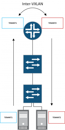
I've recently started working on a project focused on EVPN-VXLAN based on Juniper technology. I figured I'd take the opportunity to share some experiences specifically around inter-VXLAN routing. Inter-VXLAN routing can be useful when passing traffic between different tenants. For example, you may have a shared-services tenant that needs to be accessed by a number of different customer tenants whilst not allowing reachability between customer tenants. By enabling inter-VXLAN routing on the MX we can use various route-leaking techniques and policy to provide a technical point of control.
There are plenty of really great resources available for EVPN-VXLAN so I won't delve into any great depths, rather I'll jump straight into the topology and configs to enable inter-VXLAN routing in a EVPN-VXLAN environment. A great reference document can be found here, where you'll find a detailed overview of EVPN-VXLAN and a number of deployment scenarios.
The design that I'm working on is based on Juniper QFX and MX technology with QFX performing Spine and Leaf functions. Whilst MX is performing Core VXLAN L3 gateway functions. My initial design incorporated Juniper QFX10000 at a collapsed spine and core layer. However, due to customer requirements, I have decided to go with QFX5110-48s at the leaf, QFX5110-36q at the spine with MX at the core. The reason for this is to provide a common aggregation for a number of different infrastructure pods.
For the purpose of this lab I'm using QFX5100 switches whilst waiting for QFX5110 to ship. Luckily I have quite a few QFX5100s in the lab. I'm using a Juniper MX80 for the core. In terms of functions, the QFX5100s are fine as all I really need at the moment is VXLAN L2 and EVPN of course.
Note. QFX5100 cannot support VXLAN L3 gateway. The QFX5110, however, has this feature on the roadmap currently scheduled for 17.3 JUNOS. This is made possible by the latest gen Broadcom Trident II+ chipset.
Here's the EVPN-VXLAN topology:
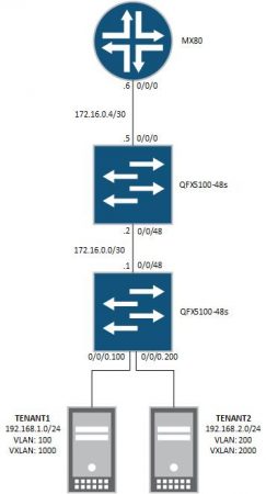
Core - MX80 - 17.1R1.8
Spine - QFX5100-48s - 17.1R1.8
Leaf - QFX5100-48s - 17.1R1.8
Underlay
Outside of the all the usual configuration elements such as system, interface etc all we really need to do is enable the exchange of loopback information. There are a number of options available here but I have opted for a simple eBGP design. Policy is used to leak lo0 into BGP. The default BGP import policy will deal with the exchange at the spine QFX. I have configured BGP multipath and forwarding-plane load-balancing as I will be adding additional devices to the setup in due course. The following config snippets have been taken from the leaf QFX but similar config should be applied to all nodes in the setup.
Routing-options
As we are using eBGP, each node in the fabric will be assigned a unique private AS. We also explicitly define lo0 address as the router-id. Lastly, we apply a load-balance policy as I will be adding additional devices at a later date.
{master:0}[edit]lab@qfx-leaf> show routing-options}router-id 10.0.255.1;autonomous-system 65001;forwarding-table {export load-balance;}
Underlay eBGP session(s)
This is just a simple eBGP session used to exchange loopback info. Physical interface peering should be used. Multipath is again enabled to support additional devices at a later date.
{master:0}[edit]lab@qfx-leaf> show protocols bgpgroup underlay {type external;export lo0-export;multipath;neighbor 172.16.0.2 {description spine;peer-as 65002;}}
Policy - lo0-export
This policy matches any direct interfaces with a /32 mask i.e. lo0.
Policy - load-balance
This policy is in place to support additional devices at a later date.
{master:0}[edit]lab@qfx-leaf> show policy-optionspolicy-statement lo0-export {term 1 {from {family inet;protocol direct;route-filter 0.0.0.0/0 prefix-length-range /32-/32;}then accept;}}policy-statement load-balance {term 1 {then {load-balance per-packet;}}}
Verify BGP session establishment
From the pov of the leaf QFX we have a single eBGP session with the spine QFX. On the spine QFX we will have two eBGP sessions. And lastly the core MX will have a single session.
{master:0}lab@qfx-leaf> show bgp summaryGroups: 1 Peers: 1 Down peers: 0Table Tot Paths Act Paths Suppressed History Damp State Pendingbgp.evpn.00 0 0 0 0 0inet.02 2 0 0 0 0Peer AS InPkt OutPkt OutQ Flaps Last Up/Dwn State|#Active/Received/Accepted/Damped...172.16.0.2 65002 21690 21686 0 0 6d 19:16:20 Establinet.0: 2/2/2/0
Confirm loopback information is present in inet.0 routing table
A quick check to ensure we have loopbacks in inet.0.
{master:0}lab@qfx-leaf> show route 10.0.255/24inet.0: 8 destinations, 8 routes (8 active, 0 holddown, 0 hidden)+ = Active Route, - = Last Active, * = Both10.0.255.1/32 *[Direct/0] 6d 00:40:37> via lo0.010.0.255.2/32 *[BGP/170] 6d 00:39:25, localpref 100AS path: 65002 I, validation-state: unverified> to 172.16.0.2 via et-0/0/48.010.0.255.3/32 *[BGP/170] 6d 00:39:25, localpref 100AS path: 65002 65003 I, validation-state: unverified> to 172.16.0.2 via et-0/0/48.0
Overlay
Now that we have loopback information available in inet.0 we can go ahead and configure eBGP overlay with EVPN signaling between the leaf QFX and the core MX. We will also configure the initial parameters for EVPN-VXLAN on the leaf QFX at this stage. Tenant specific config will come a bit later on. The following depicts the underlay and overlay BGP design:
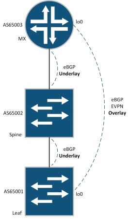
eBGP overlay with EVPN signaling
This is a mutual eBGP session between leaf QFX and core MX. The spine QFX is not required to participate in the eBGP EVPN overlay. As these sessions are formed over multiple hops we need to change the default TTL behavior with the multihop knob and also set lo0 as the local-address. Family EVPN signaling is the only NLRI required.
{master:0}[edit]lab@qfx-leaf# show protocols bgp<output omitted>group overlay {type external;multihop {ttl 2;}local-address 10.0.255.1;family evpn {signaling;}neighbor 10.0.255.3 {description core;peer-as 65003;}}
Configure initial EVPN parameters
We're now going to configure some initial EVPN settings on the leaf QFX. The core MX will have similar config but it will be entirely contained within a routing-instance so we will cover that in the tenant overlay section below. Firstly we need to define the EVPN encapsulation as VXLAN. Next, define how to handle BUM traffic. Lastly, define which VNIs should be included in the virtual switch. For the sake of demo we're enabling all. Note. When specifying extended-vni-list JUNOS defaults to multicast-mode ingress-replication.
{master:0}[edit]lab@qfx-leaf# show protocols evpnencapsulation vxlan;multicast-mode ingress-replication;extended-vni-list all;
Switch-options
This is where we configure parameters for the default EVPN switch. Again, this is only applicable to the leaf QFX. We'll configure the core MX in the next section. We need to set VTEP to source from lo0.0. It is important to ensure route-distinguishers are unique across the domain in a iBGP environment. As we are using eBGP it is not necessary but nevertheless we are using the lo0 IP address. Lastly, we need to define vrf-import and vrf-target. vrf-target is used to tag type-1, type-2 and type-3 EVPN routes. However, we will manually override route-targets for type-2 and type-3 EVPN routes later. vrf-import defines which route targets will be imported into the EVPN.
{master:0}[edit]lab@qfx-leaf# show switch-optionsvtep-source-interface lo0.0;route-distinguisher 10.0.255.1:1;vrf-import EVPN-IMPORT;vrf-target {target:1234:1234;auto;}
Policy - EVPN-IMPORT
Now let's create the EVPN-IMPORT policy. We also need to configure a community for EVPN routes.
{master:0}[edit]lab@qfx-leaf# show policy-option<output omitted>policy-statement EVPN-IMPORT {term leaf {from community leaf;then accept;}term reject {then reject;}}community leaf members target:1234:1234;
Tenant Overlay - Leaf QFX
Ok so now we're finally going to configure some customer overlays. On the QFX leaf this involves creating customer specific VNIs and attaching to a client port. We'll also update our EVPN-IMPORT policy.
Define tenant VNI
Define two VNIs and assign vrf-targets. This overrides type-2 and type-3 EVPN route types as mentioned previously.
{master:0}[edit]lab@qfx-leaf# show protocols evpnvni-options {vni 1000 {vrf-target target:1:100;}vni 2000 {vrf-target target:1:200;}}encapsulation vxlan;multicast-mode ingress-replication;extended-vni-list all;
Attach interface to VNI
Now we need to map our TENANT1 and TENANT2 interfaces to VNIs.
{master:0}[edit]lab@qfx-leaf# show vlansVXLAN100 {interface ge-0/0/0.100;vxlan {vni 1000;ingress-node-replication;}}VXLAN200 {interface ge-0/0/0.200;vxlan {vni 2000;ingress-node-replication;}}
Update EVPN-IMPORT policy
Lastly, for the leaf QFX we need to update our EVPN-IMPORT policy to include the two new VNIs we've just added. Associated communities are also created.
{master:0}[edit]lab@qfx-leaf# show policy-options<output omitted>policy-statement EVPN-IMPORT {term leaf {from community leaf;then accept;}term tenant1 {from community tenant1;then accept;}term tenant2 {from community tenant2;then accept;}term reject {then reject;}}community leaf members target:1234:1234;community tenant1 members target:1:100;community tenant2 members target:1:200;
Tenant Overlay - Core MX
On the core MX we will create a number of routing-instances, two per customer tenant; one for EVPN virtual-switch and the other for L3 GW. IRB interfaces are used to provide L3 gateway.
Customer tenant virtual-switch routing-instance
We'll start off by creating a virtual-switch routing-instance for each of our customer overlays. We need to set lo0.0 as the VTEP source. Note. you must ensure that logical unit 0 is defined here otherwise the associated IRB will fail to come up. On the MX, we also ensure that unique route-distinguishers are used. In addition to this, we define a vrf-import policy to import only the routes that belong to the tenant. vrf-target is used to ensure that the MX will import and export routes for this virtual-switch with the same target. At the protocol evpn stanza set vxlan encapsulation, explicitly define the VNI for the customer tenant and define the multicast-mode. Lastly, we need to create an L2 bridge-domain. Within the bridge-domain we need to add a vlan-id (it seems this bears no relevance but is needed for config check-out). A routing-interface is bound and we again explicitly define the VNI for the customer tenant.
[edit]lab@mx80-core# show routing-instancesTENANT1-VS {vtep-source-interface lo0.0;instance-type virtual-switch;route-distinguisher 10.0.255.3:100;vrf-import TENANT1-VS-IMPORT;vrf-target target:1:100;protocols {evpn {encapsulation vxlan;extended-vni-list 1000;multicast-mode ingress-replication;}}bridge-domains {bd1000 {vlan-id 66;routing-interface irb.1000;vxlan {vni 1000;ingress-node-replication;}}}}TENANT2-VS {vtep-source-interface lo0.0;instance-type virtual-switch;route-distinguisher 10.0.255.3:200;vrf-import TENANT2-VS-IMPORT;vrf-target target:1:200;protocols {evpn {encapsulation vxlan;extended-vni-list 2000;multicast-mode ingress-replication;}}bridge-domains {bd2000 {vlan-id 200;routing-interface irb.2000;vxlan {vni 2000;ingress-node-replication;}}}}
Customer tenant VRF routing-instance
Next up we need to configure a VRF routing-instance for each customer-tenant. These routing-instances will host the L3 IRB interfaces required to provide L3 gateway. According to documentation, a loopback interface is required to process EVPN packets. You may notice that the vrf-targets set below match their associated virtual-switch targets above. However, this is not required and the values can be unique.
[edit]lab@mx80-core# show routing-instancesTENANT1-L3 {instance-type vrf;interface irb.1000;interface lo0.1;route-distinguisher 1:1;vrf-target target:1:100;}}TENANT2-L3 {instance-type vrf;interface irb.2000;interface lo0.2;route-distinguisher 2:2;vrf-target target:1:200;}}
irb L3 interface
Let's now quickly create the two irb interfaces that were defined above. Crucially we are going to define a virtual-gateway-address. This essentially creates an anycast gateway to support multiple core node gateways. Whilst this is not currently applicable in the existing setup I will be adding additional core nodes at a later date.
[edit]lab@mx80-core# show interfaces irbunit 1000 {family inet {address 192.168.1.253/24 {virtual-gateway-address 192.168.1.254;}}}unit 2000 {family inet {address 192.168.2.253/24 {virtual-gateway-address 192.168.2.254;}}}
Policy - TENANT-VS-IMPORT
We now need to create an import policy for each of our tenant virtual-switch routing-instances. We'll also define communities for each tenant and the default evpn switch.
[edit]lab@mx80-core# show policy-optionspolicy-statement TENANT1-VS-IMPORT {term leaf {from community leaf;then accept;}term tenant1 {from community tenant1;then accept;}}policy-statement TENANT2-VS-IMPORT {term leaf {from community leaf;then accept;}term tenant2 {from community tenant2;then accept;}}community leaf members target:1234:1234;community tenant1 members target:1:100;community tenant2 members target:1:200;
Verification
Now let's check the routing-table and verify reachability to the gateway from each of our tenants. The tenants have been pre-configured with a default route with the next-hop pointing towards the virtual-gateway-address. Note. The virtual-gateway will not reply to requests thus we have to send traffic to the irb address.
{master:0}lab@POC-EX-SWITCH> show route table TENANT1TENANT1.inet.0: 3 destinations, 3 routes (3 active, 0 holddown, 0 hidden)+ = Active Route, - = Last Active, * = Both
0.0.0.0/0 *[Static/5] 1w0d 23:49:18> to 192.168.1.254 via ge-0/1/0.100192.168.1.0/24 *[Direct/0] 1w1d 01:16:31> via ge-0/1/0.100192.168.1.1/32 *[Local/0] 1w1d 01:16:31Local via ge-0/1/0.100
{master:0}lab@POC-EX-SWITCH> ping 192.168.1.253 routing-instance TENANT1 count 5PING 192.168.1.253 (192.168.1.253): 56 data bytes64 bytes from 192.168.1.253: icmp_seq=0 ttl=64 time=9.867 ms64 bytes from 192.168.1.253: icmp_seq=1 ttl=64 time=1.063 ms64 bytes from 192.168.1.253: icmp_seq=2 ttl=64 time=1.078 ms64 bytes from 192.168.1.253: icmp_seq=3 ttl=64 time=1.078 ms64 bytes from 192.168.1.253: icmp_seq=4 ttl=64 time=1.120 ms
--- 192.168.1.253 ping statistics ---5 packets transmitted, 5 packets received, 0% packet lossround-trip min/avg/max/stddev = 1.063/2.841/9.867/3.513 ms
{master:0}lab@POC-EX-SWITCH> show route table TENANT2TENANT2.inet.0: 3 destinations, 3 routes (3 active, 0 holddown, 0 hidden)+ = Active Route, - = Last Active, * = Both
0.0.0.0/0 *[Static/5] 1w0d 23:53:29> to 192.168.2.254 via ge-0/1/0.200192.168.2.0/24 *[Direct/0] 1w1d 01:20:42> via ge-0/1/0.200192.168.2.1/32 *[Local/0] 1w1d 01:20:42Local via ge-0/1/0.200
{master:0}lab@POC-EX-SWITCH> ping 192.168.2.253 routing-instance TENANT2 count 5PING 192.168.2.253 (192.168.2.253): 56 data bytes64 bytes from 192.168.2.253: icmp_seq=0 ttl=64 time=1.218 ms64 bytes from 192.168.2.253: icmp_seq=1 ttl=64 time=1.204 ms64 bytes from 192.168.2.253: icmp_seq=2 ttl=64 time=2.594 ms64 bytes from 192.168.2.253: icmp_seq=3 ttl=64 time=1.112 ms64 bytes from 192.168.2.253: icmp_seq=4 ttl=64 time=1.038 ms
--- 192.168.2.253 ping statistics ---5 packets transmitted, 5 packets received, 0% packet lossround-trip min/avg/max/stddev = 1.038/1.433/2.594/0.584 ms
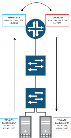
Inter-VXLAN Routing
Finally, let's enable inter-vxlan routing. This is achieved by configuring route-leaking between the VRF routing-instances on the core MX.
Policies - TENANT_VRF_IMPORT
Create an import policy for each customer tenant VRF routing-instance to accept its peer route-target.
[edit]lab@mx80-core# show policy-options<output omitted>policy-statement TENANT1_VRF_IMPORT {term 1 {from community tenant2;then accept;}}policy-statement TENANT2_VRF_IMPORT {term 1 {from community tenant1;then accept;}}<output omitted>
Apply VRF import policy and update routing-options
Lastly, we need to apply the newly created VRF_IMPORT policies and enable auto-export under routing-options of the routing-instance. This enables IP connectivity between tenants that are connected directly to the overlay.
[edit]lab@mx80-core# show routing-instances<output omitted>TENANT1-L3 {instance-type vrf;interface irb.1000;interface lo0.1;route-distinguisher 1:1;vrf-import TENANT1_VRF_IMPORT;vrf-target target:1:100;routing-options {auto-export;}}TENANT2-L3 {instance-type vrf;interface irb.2000;interface lo0.2;route-distinguisher 2:2;vrf-import TENANT2_VRF_IMPORT;vrf-target target:1:200;routing-options {auto-export;}}
Verification
Firstly, let's check TENANT1-L3's routing table. We can now see that Tenant 2's 192.168.2.0/24 prefix is reachable via irb.2000.
[edit]lab@mx80-core# exitExiting configuration modelab@mx80-core> show route table TENANT1-L3.inet.0TENANT1-L3.inet.0: 7 destinations, 7 routes (6 active, 0 holddown, 1 hidden)+ = Active Route, - = Last Active, * = Both192.168.1.0/24 *[Direct/0] 00:39:30> via irb.1000192.168.1.253/32 *[Local/0] 00:39:30Local via irb.1000192.168.2.0/24 *[Direct/0] 00:03:08> via irb.2000192.168.2.253/32 *[Local/0] 00:03:08Local via irb.2000192.168.11.0/24 *[Direct/0] 00:39:30> via ge-1/0/0.1001192.168.11.2/32 *[Local/0] 00:39:30Local via ge-1/0/0.1001
Now we are able to ping between the customer tenant hosts.
{master:0}lab@POC-EX-SWITCH> ping 192.168.2.1 routing-instance TENANT1 source 192.168.1.1 count 5PING 192.168.2.1 (192.168.2.1): 56 data bytes64 bytes from 192.168.2.1: icmp_seq=0 ttl=63 time=1.402 ms64 bytes from 192.168.2.1: icmp_seq=1 ttl=63 time=1.121 ms64 bytes from 192.168.2.1: icmp_seq=2 ttl=63 time=1.136 ms64 bytes from 192.168.2.1: icmp_seq=3 ttl=63 time=1.139 ms64 bytes from 192.168.2.1: icmp_seq=4 ttl=63 time=1.190 ms--- 192.168.2.1 ping statistics ---5 packets transmitted, 5 packets received, 0% packet lossround-trip min/avg/max/stddev = 1.121/1.198/1.402/0.105 ms
