Demo – SR Topology Independent Loop Free Alternate
Diagram:
(For this lab, you need to load the initial configuration named “lab49-initial” onto the devices before going through the task lists. The final configuration/solution for this lab (lab49-final) can also be loaded onto the devices. For more information about accessing our labs and/or loading the configuration onto the devices, please refer to the lab instructions section in the course introduction chapter.)
Tasks:
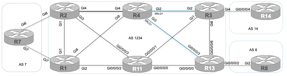
- Configure IS-IS network type as point-to-point for all the segment in the service provider core network. Adjust metric as below.
- Gi0/0/0/0 on R13 – Metric 50
- Gi3 on R2 – Metric 30
- Configure segment routing with SRGB range of 20000-23999 on all the devices.
- Configure TI-LFA feature on R4 to protect link between R4 and R3. Use SRLG-disjoint to avoid Gi3 as an alternate link.
- Configure TI-LFA feature on R13 to protect failure of R11 node.
Technology Overview:
Topology Independent Loop-Free Alternate is a mechanism to protect link/node by utilizing segment routing that allows us to deploy link/node protection where the pre-calculated backup path is maintained in the forwarding level so that the traffic could be re-routed within a millisecond. The CEF table maintains a repair path that is permanently served without having to switch it over to the re-optimized path. On contrary, RSVP based TE solution also provides FRR but with some operational differences. Also, the number of label impositions is minimized with the TI-LFA solution. In addition, the earlier versions of LFA, RLFA which were topology dependent couldn’t provide loop-free alternate paths in some instances. But, the TI-LFA solution has segment routing where it utilizes Prefix-SID and Adjacency-SID for the re-route of the traffic.
With TI-LFA we can use a number of tiebreakers like SRLG disjoint where two links sharing the same infrastructure could be excluded from the feasible backup path. It has line card level exclusion during pre-calculation of the backup path and installation within the CEF table. The first node where we define protection of a link of the node is called PLR (Point of Local Repair) and the nearest nodes from the PLR are known as P space nodes as they are presumed to have no possibility to route back to PLR using a protected link. There is another portion, called Q space which is usually nearest to the destination that can not route back to the PLR by using alternate or non-protected links, this is how the loop is avoided. Unlike earlier versions of LFA, the TI-LFA allows the PLR to create a tunnel to the P space node where the Prefix-SID for P node would be used to steer traffic whenever it is used as an alternate path during failure. The P node sends the traffic to the Q node by using Adjacency SID.
Detailed Explanation:
As per the task requirement, we are asked to enable SRLG on R4 for its interfaces to R3 and R13 where the primary interface should be protected with TI-LFA. Once we bind the interfaces in a single SRLG group identifier, they can not be used as a fallback to each other which we will see in the demonstration. Also, we are asked to configure R13 to protect against failure of R11, i.e. node protection. In order to accomplish this, we need to use a tie-breaker.
Configuration:
R1:

enable
configure ter
interface GigabitEthernet1
 isis network point-to-point
!
interface GigabitEthernet2
 isis network point-to-point
!
interface GigabitEthernet8
 isis network point-to-point
!
router isis 1
 metric-style wide
 segment-routing mpls
!
segment-routing mpls
 global-block 20000 23999
 !
 connected-prefix-sid-map
  address-family ipv4
   1.1.1.1/32 index 1 range 1
  exit-address-family
 !
 segment-routing mpls
!
end

R2:

enable
configure ter
interface GigabitEthernet1
 isis network point-to-point
!
interface GigabitEthernet3
 isis network point-to-point
 isis metric 30
!
interface GigabitEthernet4
 isis network point-to-point
!
router isis 1
 metric-style wide
 segment-routing mpls
!
segment-routing mpls
 global-block 20000 23999
 !
 connected-prefix-sid-map
  address-family ipv4
   2.2.2.2/32 index 2 range 1
  exit-address-family
 !
 segment-routing mpls
!
end


R3:

enable
configure ter
interface GigabitEthernet1
 isis network point-to-point
!
interface GigabitEthernet2
 isis network point-to-point
!
interface GigabitEthernet6
 isis network point-to-point
!
router isis 1
 metric-style wide
 segment-routing mpls
!
segment-routing mpls
 global-block 20000 23999
 !
 connected-prefix-sid-map
  address-family ipv4
   3.3.3.3/32 index 3 range 1
  exit-address-family
 !
 segment-routing mpls
!
end


R4:

enable
configure ter
interface GigabitEthernet2
 srlg gid 1
 isis network point-to-point
 isis fast-reroute ti-lfa protection level-2
!
interface GigabitEthernet3
 srlg gid 1
 isis network point-to-point
!
interface GigabitEthernet4
 isis network point-to-point
!
!
interface GigabitEthernet8
 isis network point-to-point
!
router isis 1
 metric-style wide
 segment-routing mpls
 fast-reroute per-prefix level-2 all
 fast-reroute tie-break level-2 srlg-disjoint 200
!
segment-routing mpls
 global-block 20000 23999
 !
 connected-prefix-sid-map
  address-family ipv4
   4.4.4.4/32 index 4 range 1
  exit-address-family
 !
 segment-routing mpls
!
end

R11:

enable
configure ter
router isis 1
 address-family ipv4 unicast
  metric-style wide
  segment-routing mpls
 !
 interface Loopback0
  address-family ipv4 unicast
   prefix-sid index 11
  !
 !
 interface GigabitEthernet0/0/0/0
  point-to-point
  !
 !
 interface GigabitEthernet0/0/0/1
  point-to-point
  !
 !
 interface GigabitEthernet0/0/0/2
  point-to-point
  !
 !
 interface GigabitEthernet0/0/0/3
  point-to-point
  !
 !
!
commit


R13:

enable
configure ter
router isis 1
 address-family ipv4 unicast
  metric-style wide
  segment-routing mpls
 !
 interface Loopback0
  address-family ipv4 unicast
   prefix-sid index 13
  !
 !
 interface GigabitEthernet0/0/0/0
  point-to-point
  address-family ipv4 unicast
   fast-reroute per-prefix
   fast-reroute per-prefix tiebreaker node-protecting index 100
   fast-reroute per-prefix ti-lfa
  !
 !
 interface GigabitEthernet0/0/0/3
  point-to-point
  address-family ipv4 unicast
   metric 50
  !
 !
 interface GigabitEthernet0/0/0/6
  point-to-point
  !
 !
!
commit
Verification:
By default, IGP follows the shortest path based on the route metric unless we signal some sort of constraint by utilizing the MPLS TE function. Even though we do not have MPLS TE in use for this demonstration, the TI-LFA which is working in conjunction with the segment routing provides a similar kind of constraint where we can exclude a link from getting installed as a pre-calculated backup link. The first thing we would want to check is the status of TI-LFA with a couple of verification commands.
R4#sh isis fast-reroute ti-lfa tunnel
Tag 1:
Fast-Reroute TI-LFA Tunnels:

Tunnel  Interface  Next Hop         End Point        Label     End Point Host
MP1     Gi8        10.1.14.1        11.11.11.11      20011     R11
MP2     Gi8        10.1.14.1        1.1.1.1          20001     R1
The tunnel is formed based on what we have configured. Since we are looking to protect interface Gi2 but excluding Gi3 by using SRLG, the possible path to get to Q space would be via R1 and R11. We can check for the CEF table to figure out the pre-installed backup route.
R4#sh ip cef 3.3.3.3
3.3.3.3/32
  nexthop 10.1.34.3 GigabitEthernet2 label [implicit-null|20003]-(local:20003)
    repair: attached-nexthop 11.11.11.11 MPLS-SR-Tunnel1
The Prefix-SID can be observed that is required to forward traffic to the final egress PE router where the backup route is via auto-provisioned tunnel interface towards the PQ node.
R7#traceroute 14.14.14.14 sou l0
Type escape sequence to abort.
Tracing the route to 14.14.14.14
VRF info: (vrf in name/id, vrf out name/id)
  1 10.1.27.2 1 msec 1 msec 1 msec
  2 10.1.24.4 [MPLS: Labels 20003/101 Exp 0] 3 msec 2 msec 2 msec
  3 10.1.143.3 [MPLS: Label 101 Exp 0] 1 msec 1 msec 1 msec
  4 10.1.143.14 13 msec *  33 msec
The trace report indicates that the primary path via the R4-R3 link is being used to deliver customer VPN traffic to its final destination. Now, shut the link between R3-R4 and check with the traceroute operation.
R4(config)#inter gi2
R4(config-if)#shut

R7#traceroute 14.14.14.14 sou l0
Type escape sequence to abort.
Tracing the route to 14.14.14.14
VRF info: (vrf in name/id, vrf out name/id)
  1 10.1.27.2 2 msec 1 msec 1 msec
  2 10.1.24.4 [MPLS: Labels 20003/101 Exp 0] 2 msec 1 msec 2 msec
  3 10.1.14.1 [MPLS: Labels 20011/20003/101 Exp 0] 3 msec 1 msec 1 msec
  4 10.1.111.11 [MPLS: Labels 20003/101 Exp 0] 20 msec 15 msec 9 msec
  5 10.1.143.3 [MPLS: Label 101 Exp 0] 2 msec 2 msec 1 msec
  6 10.1.143.14 9 msec *  6 msec
One more label stack can be observed from the above output where the top of the stack is used to re-route traffic till the PQ node, R11 which is the auto-created tunnel endpoint as well. By the time the labeled packet reaches its first destination, R11. The label is popped by the R1 due to signaling of the implicit null label. Since the final destination is connected to R3, the Prefix-SID of R3 is being used from the initial point to the ultimate point, i.e. ingress to egress LSR. Let’s not forget that we have another shortest path that could be installed as a backup but we have used SRLG to exclude the R4-R13 link from the possible candidate to be the alternate route.
Now, let’s go to R13 to check the node protection function.
RP/0/RP0/CPU0:R13#sh isis fast-reroute 1.1.1.1/32
Tue Sep 28 18:37:35.926 UTC

L2 1.1.1.1/32 [30/115]
     via 10.1.131.11, GigabitEthernet0/0/0/0, R11, SRGB Base: 20000, Weight: 0
       Backup path: TI-LFA (node), via 10.1.133.3, GigabitEthernet0/0/0/6 R3, SRGB Base: 20000, Weight: 0, Metric: 40
         P node: R4.00 [4.4.4.4], Label: 20004
         Prefix label: 20001
         Backup-src: R1.00
As we can see, the node protection is in operation. Even though R4 is far from the route metric point of view, R11 is not kept as a backup since we are protecting node, failure of R11 itself.
R8#traceroute 7.7.7.7 sou l0
Type escape sequence to abort.
Tracing the route to 7.7.7.7
VRF info: (vrf in name/id, vrf out name/id)
  1 10.1.138.13 5 msec 8 msec 2 msec
  2 10.1.131.11 [MPLS: Labels 20001/111 Exp 0] 48 msec 17 msec 8 msec
  3 10.1.17.1 [MPLS: Label 111 Exp 0] 3 msec 3 msec 3 msec
  4 10.1.17.7 3 msec *  3 msec

RP/0/RP0/CPU0:R13#sh ip cef 1.1.1.1/32
Tue Sep 28 18:40:06.388 UTC
1.1.1.1/32, version 2898, labeled SR, internal 0x1000001 0x81 (ptr 0xe1c3f78) [1], 0x0 (0xe3884a8), 0xa28 (0xf2aa180)
 Updated Sep 28 18:35:57.917
 remote adjacency to GigabitEthernet0/0/0/0
 Prefix Len 32, traffic index 0, precedence n/a, priority 1
   via 10.1.131.11/32, GigabitEthernet0/0/0/0, 13 dependencies, weight 0, class 0, protected [flags 0x400]
    path-idx 0 bkup-idx 1 NHID 0x0 [0xf2ef190 0x0]
    next hop 10.1.131.11/32
     local label 20001      labels imposed {20001}
   via 10.1.133.3/32, GigabitEthernet0/0/0/6, 13 dependencies, weight 0, class 0, backup (TI-LFA) [flags 0xb00]
    path-idx 1 NHID 0x0 [0xf107140 0x0]
    next hop 10.1.133.3/32, Repair Node(s): 4.4.4.4
    remote adjacency
     local label 20001      labels imposed {20004 20001}
The preceding outputs give us the required information on the primary and the backup path on both the FRR database followed by the CEF table. R4 is the repair node that protects against the failure of R11.
RP/0/RP0/CPU0:R13#show mpls forwarding labels 20001 detail
Tue Sep 28 18:45:47.229 UTC
Local  Outgoing    Prefix             Outgoing     Next Hop        Bytes
Label  Label       or ID              Interface                    Switched
------ ----------- ------------------ ------------ --------------- ------------
20001  20001       SR Pfx (idx 1)     Gi0/0/0/0    10.1.131.11     0
     Updated: Sep 28 18:43:27.213
     Path Flags: 0x400 [  BKUP-IDX:1 (0xf2ef190) ]
     Version: 2951, Priority: 1
     Label Stack (Top -> Bottom): { 20001 }
     NHID: 0x0, Encap-ID: N/A, Path idx: 0, Backup path idx: 1, Weight: 0
     MAC/Encaps: 4/8, MTU: 1500
     Outgoing Interface: GigabitEthernet0/0/0/0 (ifhandle 0x01000018)
     Packets Switched: 0

       20004       SR Pfx (idx 1)     Gi0/0/0/6    10.1.133.3      0            (!)
     Updated: Sep 28 18:43:27.213
     Path Flags: 0xb00 [  IDX:1 BKUP, NoFwd ]
     Version: 2951, Priority: 1
     Label Stack (Top -> Bottom): { 20004 20001 }
     NHID: 0x0, Encap-ID: N/A, Path idx: 1, Backup path idx: 0, Weight: 0
     MAC/Encaps: 4/12, MTU: 1500
     Outgoing Interface: GigabitEthernet0/0/0/6 (ifhandle 0x01000020)
     Packets Switched: 0
     (!): FRR pure backup

  Traffic-Matrix Packets/Bytes Switched: 0/0
The Prefix-SID of R4 can be observed here because this is the repair node and whenever there is a failure, an additional label stack of the repair node will be imposed to redirect traffic towards the repair node.
Let’s shut the link to a similar failure of R11.
RP/0/RP0/CPU0:R11(config)#inter gi0/0/0/0
RP/0/RP0/CPU0:R11(config-if)#shut
RP/0/RP0/CPU0:R11(config-if)#inter gi0/0/0/1
RP/0/RP0/CPU0:R11(config-if)#shut
RP/0/RP0/CPU0:R11(config-if)#inter gi0/0/0/2
RP/0/RP0/CPU0:R11(config-if)#shut
RP/0/RP0/CPU0:R11(config-if)#inter gi0/0/0/3
RP/0/RP0/CPU0:R11(config-if)#shut
RP/0/RP0/CPU0:R11(config-if)#commit

R8#traceroute 7.7.7.7 sou l0
Type escape sequence to abort.
Tracing the route to 7.7.7.7
VRF info: (vrf in name/id, vrf out name/id)
  1 10.1.138.13 8 msec 25 msec 33 msec
  2 10.1.133.3 [MPLS: Labels 20001/111 Exp 0] 2 msec 2 msec 2 msec
  3 10.1.34.4 [MPLS: Labels 20001/111 Exp 0] 2 msec 2 msec 2 msec
  4 10.1.17.1 [MPLS: Label 111 Exp 0] 1 msec 2 msec 1 msec
  5 10.1.17.7 1 msec *  3 msec